First tests with my last build of a tube regenerative receiver.
The original design is by Vladimir Novichkov (please look for thread "6AS6 regen, mk2" on http://theradioboard.com for a detailed description).
I opted for a simplified build (no varactor-based fine tuning, no tube-based AF amp, no AGC). Still, probably one of the ugliest buids ever seen :) Anyway, after some tweaking it's starting to work.
The global tuning range is about 3600 kHz to 10700 kHz.
Yes, I need a reduction drive for the "band spread" capacitor, otherwise it will drive me crazy very soon :)
The small card at the centre of my kitchen table is a small JFET-based audio preamplifier.
The hairy hand appering in the video is not King Kong's, it's mine 😁
I bought a LS-166/U military loudspeaker in good general conditions recently. According to labels on it, my LS-166/U was made in Italy by LA.RI.MA.R.T., in Rome.
I bought the LS-166/U with the aim of adapting it as the external loudspeaker for my russian R-326 military receiver.
As you may well know, the R-326 (or P-326 according to the russian alphabet) is a nice small receiver, which can operate both from batteries and from AC mains (by means of its power supply). It started to be produced in early '60s. It employs 19 miniature tubes and requires only about 1.5A at 2.5V to operate, which is surprisingly a low power requirement for a tube receiver of its complexity.
The R-326 receiver (from http://air-radiorama.blogspot.com)
The R-326 does not feature an internal speaker. It has a 600 ohms audio output, in the form of a bipolar socket in the lower part of the front panel, that can be used for connecting both heaphones and a 600 ohms external speaker.
Let me say that the original, heavy duty, military headphones that came with my R-326 are not the best you could desire in terms of comfort. So I started to think about how to connect more modern, light and comfortable low-impedance headphones to the radio. First, I looked around for a 600 ohms to 8 ohms transformer to build a simple impendance and connector adapter, then I thought that it could be nice sometimes to have a chance to listen to the radio by an external loudspeaker, possibily a military one. The LS-166/U appeared to be well suitable for my purposes: 600 ohms input impedance, an internal impedance transformer with 8 ohms output, a rotary switch that could well be used to redirect the output to a stereo jack (to be added) for headphones. Finally, there were enough room to add a volume control.
In fact, the R-326 does not offer a real AF gain control on its front panel. Rather, the output audio level can be controlled by acting on the RF gain control. In practice, it is expected that the audio level be controlled externally, on the loudspeaker.
The LS-166/U detailed information can be found here: LS-166/U
This is the original schematics of the unit:
This is how I have modified it (I hope it is readable):
I removed the original cable (terminated by the U-77/U connector) and replaced it with a robust bipolar cable terminated by two very simple banana plugs, suitable for the R-326 audio output socket.
Then I re-wired the internal connection to adapt for the addition of a 100 ohms wire potentiometer and a stereo 6.3 mm jack.
NOTE: after first period of usage, I preferred to re-wire the volume control as a voltage divider, in parallel with the secondary of the impedance transformer. The original series connection did not allow to completely silent the audio output.
This is a short video showing the unit while working connected to the R-326 receiver.
Here below a brief photo story of my modifications.
The re-wired internal connections
The added audio level control and headphones jack
The original switch now selects speaker or headphhones
This one will be probably the last in a series of posts around my "next" regenerative receiver (as I called it when the project began). You can find my previous posts on the same subject by looking backwards from here: My "next" regen receiver - Schematic diagram of the RF stages.
Below you will find the link to a YouTube video showing some tests that I did with the radio at night (say around 21:00 CEST), just after having completed the construction. Thank you for reading!
Here below I copy the schematic diagram of the RF stages of my regen receiver in its current configuration. As said in my latest post on the same subject, the design of the regenerative detector was copied from David Newkirk's web page Receivers for Watching 7120 kHz, with only some minor modifications. From very first tests, it seems that the receiver can work acceptably well from day one, apart from normal tweaking and some stability issues (due to non-ideal mechanical construction). I will post soon a short video clip of the radio in operation.
The actual frequency range (as measured by putting the detector in oscillation and looking for the tone with a Tecsun PL-660 portable in SSB mode) is from about 2400 kHz up to about 7960 kHz.
My reverse computation give about 28 pF to 310 pF for the range of the combined bandset and bandspread variable capacitors; and about 14 uH for the inductance of the tuning coil (I expected 8 uH, based on construction data). I will evaluate later on if it could be worth to try reducing the lower limit of the capacitance (by adding a series fixed capacitor to the bandspread varcap or by using only a single section of it) to extend the upper limit of tuning range, including for example the 31m broadcast band.
Quick update: after having posted the schematic diagram above, actually I made some experiments with the tuning range. I ended up with the decision to use only a single section of both the bandset capacitor and the bandspread capacitor. With this arrangement, the receiver can tune from about 3310 kHz to about 9325 kHz, which is fully satisfactory to me.
Now I have completed the build with the RF stages (an untuned amplifier based on a 6AK5 tube, followed by a regenerative detector based on a 12AU7 tube, wired as a pseudo-tetrode).
The RF part of the design was copied from David Newkirk's Receivers for Watching 7120 kHz, with only minor modifications that I will describe in a schematic diagram as soon as it will be stable enough after some more tests and tweaking.
Overall, the layout and the mechanics look a bit "oddish" (it is a poor-man regen, as I said). For the chassis, I used two pieces of copper clad and some pine wood. For the back panel, I cut a small rectangle of galvanized sheet and for the front panel I used a piece of aluminium sheet which was part of a dismantled surplus equipment.
My very first tests seemed encouraging: with 1-meter long antenna wire I managed to hear quite strong european broadcast signals, in a shortwave band that I couldn't identify (I have still to make a rough calibration of the tuning range/scale).
Some images follow of the receiver as it looks at present. Next post on the same subject will include the schematic diagram and a short video clip showing the radio in operation (hopefully :-)).
The coil is 22 turns of AWG18 enameled copper wire over a 1" 1/4 support. The Hartley tap wss provisionally set at 7th turn (about 1/3) from the ground side. The grey (shielded) cable goes to the AF gain pot and the black one is for the AF output jack.
Another view with the main tuning variable capacitor (Hammarlund, 140 pF per section). Mounted above on the front panel is the band spread capacitor which has an embedded 1:3 reduction drive.
The back panel has inputs for the 6,3 VAC heaters voltage and for the 150 VDC B+ voltage.
The front panel (without knobs). From left to right, top to bottom: AF gain control, band spread varcap, AF output jack, main tuning varcap, AF output switch (speaker/headphones), antenna input, RF gain control, regeneration control.
I'm just starting to collect components and utility modules for my next homebrewing project, which will be another small tube regenerative receiver.
As a starting point, it is always quite important to decide what the power supply for the receiver will be. In my case, I already had a nice vintage Ameco PS-1 tube power supply that seemed almost perfect for this purpose. However, its internal circuit needed some improvements to be made more efficient; and the existing components (in particular, the old selenium rectifier and the electrolytic filter capacitor) needed to be replaced with something newer and safer.
The original schematic diagram of the Ameco PS-1
So I put toghether a rectifier bridge on a small piece of stripboard, made by four 1N4004 diodes (each in parallel with a 10 nF ceramic bypass capacitor) and I mounted it inside the power supply box, using the same screw that held the old selenium rectifier in place. Then I replaced the existing 2 x 22 uF, 150 V electrolytic capacitor with a new 100 uF, 400 V device. I removed the RC filter, as my intention is to add proper filtering where needed in the receiver.
The final schematic diagram of the power supply is the following:
The schematic diagram of my modified Ameco PS-1
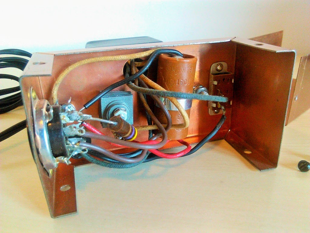
Here below a photograph showing the new internal wiring:
After having taken the image above, I added a 47 kohms, 1W bleeder resistor in parallel with the DC output.
For increased safety, I have also detached the so-called (in the Ameco PS-1 manual) "internal tie point" from pin 4 of the output connector (refer to figure below).
The modified output connector
In fact, pin 4 of the output connector was simply used as a solder lug to connect one wire from the AC mains to one end of the primary winding of transformer. You can see it in the top right area of picture above.
To have the AC main voltage present on a pin of the output connector - labeled as a very generic "internal tie point" - was a bit dangerous in my opinion!
So I detached the AC mains wire and the transponder wire from the connector and I took the oppurtunity for inserting a fuse holder between them, with a 200 mA fuse.
I finally measured the output voltages (with no load) and found about 160 V DC on B+ and about 6.5 V AC for heaters. When connected to the receiver, I suppose the B+ voltage could drop to around 140 V DC, which should be good for my project.
The short video below shows a simple method for accurate tuning of a regenerative receiver, with the help of a small portable radio with digital frequency readout, 1 kHz tuning accuracy (or better) and SSB mode.
In my video, the regen receiver is the one described in some of my recent posts.
The portable radio is the Tecsun PL-660, that I recently bought on the web to use it for my first experiments as a MW DXer.
Please consider that I have made further modifications on my tube regen, always with the kind help of some members of the regenrx list on Yahoo. The up-to-date schematics is here below:
In particular, I have removed completely the wiring that I had added for the band switch, because it had resulted in a negligible improvement as a feature, while it had caused big problems in terms of spurious resonances that led the detector to demodulate strong local FM stations.
Now the tuning range is again the original 1330 kHz to 3735 kHz, but (thanks to a suggetion from Bernd, a member of the regenrx list) I discovered that I can move it down to approx. 730-2035 kHz, without any modification in the circuit or the tuning coil, by simply inserting a small pack of four ferrite rods in the core of the coil former. I suppose that the tuning range could be moved further down in the MW band by adding another ferrite rod in the pack.
That said, please find here below my short video about a simple method for accurate tuning of a homebrewed regenerative receiver. I hope you will find it of some interest for you.
Sometimes I get attracted by small pieces of vintage electronics and - when the cost of the item is affordable for me - often I can't resist and buy these objects with a collector spirit, even if probably I will never find a practical use for them.
The above is the case of this small vintage tube radio power supply, the Ameco PS-1, that I bought last summer from US on a well known site for on-line auctions.
I put hereafter a small collection of images of the Ameco PS-1, together with its very simple schematic diagram. It can provide 6.3 VAC, 2A for tube heaters and a rectified 125VDC, 25 mA for plates (often named as the B+ voltage).
As you can see from images above, an octal socket is available for connecting the Ameco PS-1 to the user circuit. The socket is wired so that it was possible to plug the Ameco CN line of frequency converters (CN-50, CN-144, CN-220) directly into the PS-1 power supply.
I would like very much to use the Ameco as (a part of) the power supply section of a future homebrewed tube radio, most likely another simple regenerative receiver. I could also add in the receiver some better filtering on B+ and a rectifier - followed by a three terminal voltage regulator (LM7806 or similar) - for the heaters voltage and leave the Ameco PS-1 as it is. Of course, here in Italy it will require a step down transformer from 230 V of AC mains to the required 117 VAC that are used in the US, but this would not be a big problem, given the limited power to be delivered.
That's all for now, with my best wishes to all for a great year 2015.
Recently I added a band switch to my tube regen receiver, allowing to select an HF band and the lower part of MW broadcast band, in addition to the existing tuning range, which initially covered from about 1300 kHz to about 3400 kHz.
The simple modifications for adding the band switch was suggested to me by Bernd, one of the members of the great regenrx group on Yahoo. They consisted, for the HF band, in reducing the number of turns of the tuning coil from 50 to 40. For the MW band, I added a 330 uH Neosid inductor in series with the 50 turns of the tuning coil (so raising its total inductance) and added a regeneration tap at 10 turns from the ground side of the coil (for the other two bands, the tap is at 3 turns from the ground side). A 2-way, 3-position rotary switch was added on the front panel to allow an easy selection of the desired tuning range, as depicted in pictures below.
For my initial tests of the new setup, I did not check the frequency limits of the two new bands precisely (may be I will try to do this in the near future, with the help of an RF generator).
I simply went around with the tuning knobs trying to figure out how the set worked after the modification. Results are not fully satisfactory at present, in my opinion. It seems to me that the receiver in not very sensitive, both in the HF band and in the MW band. Only strong local signals produce a good audio level.
So, there is still some work to do to improve this little radio further. For the moment, I captured some moments of my tests in a couple of videos on YouTube: