The Mivar R46 is a transistor-based radio receiver from early '70s. Mivar (Milano Vichi Apparecchi Radio) was an Italian firm founded by Mr. Carlo Vichi in 1945 (initially the brand was simply VAR). The company produced TV sets and radios until 2014, when it became clear that it was no longer possible to fight (in terms of cost reduction and R&D investments) against competitors from abroad that were too bigger than Mivar.
More about Mivar history at following link: Mivar - Wikipedia
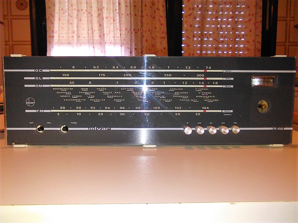
The R46 t is a 60 cm long radio receiver with LW, MW, SW and FM bands. It has volume (AF gain) and tone controls. The tuning dial is wide and nicely backlighted by four 6 V, 50 mA (0,3 W) lamps behind it. A big tuning knob and the band switching push-buttons complete the set of controls on the front panel, which also features a very nice signal level meter near the top right corner, just above the tuning knob. The push-buttons include the "Fono" mode switch, which converts the unit in simply an audio amplifier. The input connector for this mode is on the rear of the radio, in the form of a DIN 5-pins plug which also hosts the output connection for a tape recorder.
Front panel of R46 (left side)
Front panel of R46 (right side)
Other connections on the back panel are: two antenna connections, one for the SW band and one for the FM band (LW and MW use the internal ferrite antenna) and a mains voltage selector (with options for 220VAC or 125VAC).
Externally, this old radio looks simple and solid, with a very clean and quite elegant design.
The same simplicity and cleanliness can be found once you start to dismount the receiver: three screws on the rear side to remove the back panel, four screws on the bottom to free the chassis from the enclosure, four screws to remove the loudspeaker from inside the unit. Pull out the three knobs from the front panel and you can easily extract the chassis together with the loudspeaker. Very fast and safe.
Rear panel of R46 (left side)
Rear panel of R46 (right side)
The loudspeaker
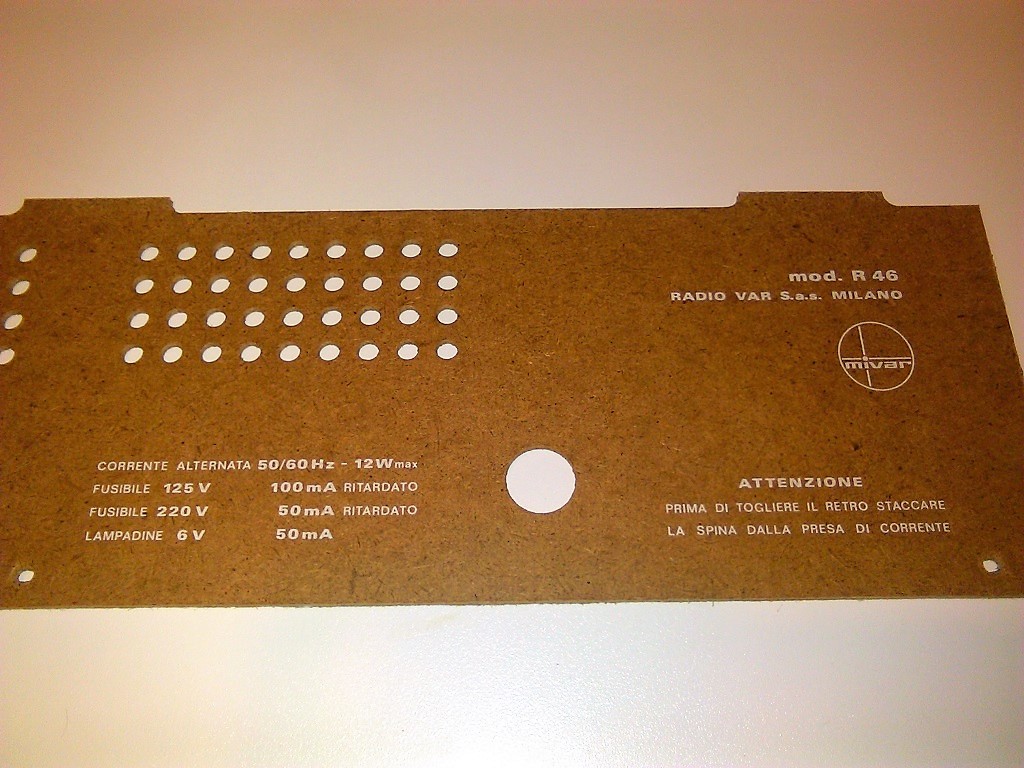
Loudspeaker removed
Also the tuning dial (which is made by glass) can be easily unlocked from the chassis.
The tuning dial of R46
Tuning dial removed
Two of the tuning dial lamps
The electronics as well looks well designed, with a very rational and clear layout of different sub-assemblies: the RF (antenna and tuning) section, the IF amplifiers, the power supply and AF amplifier. Each of the main sub-units is individually shielded and there is plenty of room to operate for repair or re-alignment.
The electronics of R46
The ferrite rod of the LW/MW antenna
The tuning capacitor, antenna and RF sections.
On the right side, the DIN connector for audio input (FONO) and output (TAPE)
The IF section on the left of the power supply and AF amplifier
Mains voltage selector on the power supply section. On the left, the IF subassembly
The bottom side of the power supply and AF amplifier section
The bottom side of the RF/IF section
The ferrite rod wich acts as the LW and MW antenna is notably long, which ensure good sensitivity. The aerial and oscillator coils are wound over plastic supports that can be easily moved along the rod to find the better position during RF alignment operations.
My unit came in good working order (apart from the probable need of a better alignment) so I decided to spend time only for some internal and external cleaning.
First, I had noticed that the volume potentiometer was soldered "quick and dirty", probably because of a replacement after a fault of the original device. So I started with trying to improve that point.
Before and after
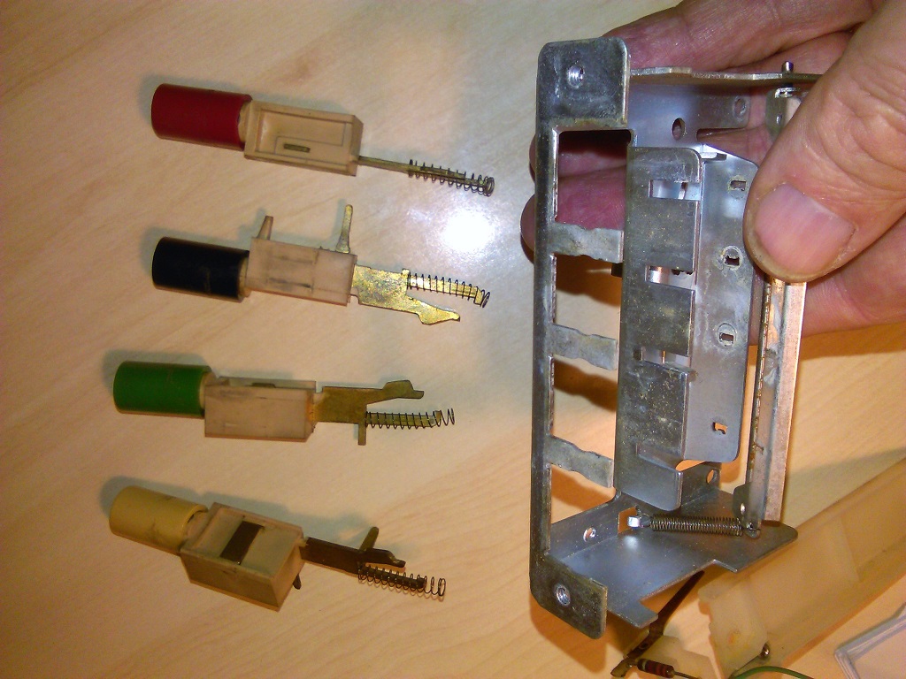
Then I had to improve the functionality of the band switch push-bottons, which showed an intermittent behaviour (quite tipical for old radios), especially on the MW band. I used a spray contact cleaner and repeatedly operated the switches until they started to work fairly well.
For general cleaning of chassis and PCBs I used 99,9% isopropyl alcohol. I applied it with the help of a paintbrush and a toothbrush. I used compressed air both before (to remove dust) and after the cleaning (to remove any excess of alcohol).
There was a small piece of plastic that went detached from the chassis. I restored it in place with a drop of cyanoacrylate adhesive.
The tuning dial and the knobs what cleaned up with some warm water and just a bit of soap.
Finally, the wooden enclosure was treated with a specific oil, by first applying it with a paintbrush and then by polishing up the surface with a soft piece of cloth.
Here below you can see the results, which are pretty satisfying to me:
This is the second part of my description of the restoration work I did on a Geloso G.256 vintage tape recorder. Please find part one at following link:
In part two, I first did a gentle cleanup of the plastic enclosure of the unit, using some drops of soap in warm water, a paintbrush and a toothbrush.
Then it was time to look after the electronics. First of all, I measured voltages on socket pins of the two main tubes, the 12AX7 and the EL95. I found that all values were more or less as specified in the service manual. I decided to order two new tubes (just to make sure the unit was equipped with good ones), then I thought I could test the behavior of the unit with an old tape reel that had come with it.
The short video below shows the result (not that bad, I thought).
By the way, the song that the unit plays in the video was recorded from an old Italian TV show named "Canzonissima", in 1972.
When new tubes arrived, I put them into the unit and made a new test with the same tape. Frankly speaking, I didn't notice any special improvements. Anyway... well, now it was equipped with new tubes and it was time to reassemble the plastic enclosure and to complete my simple restoration attempt.
The replacement tubes: a EL95 and a ECC83 (12AX7)
The video below shows the final result. At the end of the day, I was satisfied with it. It had been a pleasure to play a bit with this little piece of history of consumer electronics in Italy.
The Geloso G.256 tape recorder (also known as the "Gelosino" for its compact design) was produced for John Geloso by an Italian manufacturer (the Magnetofoni Castelli company) near Milan. At following link you can find the story (in Italian) of Magnetofoni Castelli company and its collaboration with Geloso: La storia della registrazione magnetica in Italia - Castelli, Geloso -
Just during World War II the Arrigo and Attilio Castelli brothers had patented the so called "magnetophone", a device capable to record human voice on a thin metal wire. John Geloso had the financial and industrial resources to translate that brilliant idea into a successful series of consumer products, which started with model G.239 in 1949 (that still used a metal wire) and ended with model G.682 (the last of Geloso reel to reel tape recorders, as far as I know) in 1965.
The production of the G.256 model started in 1959. Here you can find some technical details and photos of it: www.radiomuseum.org
Here an illustrated sory of the Geloso company, mainly from an ham radio point of view: Geloso story
I received my G.256 unit as a gift from a dear friend. It belonged to her beloved father and had remained unused for long time. Mainly for this reason it was not working properly anymore, in particular in its mechanical assembly.
The following photos and videos describe the restoration work I tried to do to improve the general behavior of the unit.
How it was when I first saw it. Nice external conditions.
Opening the unit
Opening the unit
The bottom side with the electronics on a PCB
The mechanical assembly
Here below is how it worked when I first inspected it on the mechanical side:
Apart from a bit of dirt, which was normal for the age of the unit, the transmission belt was clearly not working properly anymore. I ended up with replacing it with a o-ring rubber gasket which seemed to fit the purpose nicely.
The remaing work was mainly dismounting and cleaning up the different parts. For cleaning, I used 99.9% isopropyl alcohol with a paintbrush and a toothbrush. For the metal chassis and parts I used some abrasive (polishing) paste for car use, applying it with cotton, then removing any residual dirt with alcohol. Alcohol in excess was in turn removed with compressed air.
Electrical contacts was polished with a normal contact cleaner. For lubrication I used small drops of a sewing machine oil, then removing any excess with cotton and alcohol. Only for the flywheel I used a silicon-based white grease, gently applied on flywheel supports by means of a toothpick.
Some other pictures follow:
The mechanical assembly and electronics decoupled
The push-buttons dismounted
The magnetic head sub-assembly
The rev counter sub-assembly
The rev counter driving wheel
The chassis after some cleaning
The magnetic head sub-assembly after some cleaning
The electronic board after cleaning - Solder side
The electronic board after cleaning - Component side
Here below is a short video with a first test just after having reassembled the mechanical assembly and the electronics together:
The rubber of the pinch roller had a mark (clearly visible in picture below) due to the fact that the roller had remained blocked in the same position for a very long time.
To remove the mark, I mounted the pinch roller on a long screw and inserted the screw in the spindle of an electric drill, then I gently sanded it down during rotation by using a small piece of 1000 grade sandpaper. Here below you can see the results. The mark is still visible, but significantly less deep than before. I preferred non to insist too much with sandpaper to avoid any risk to put the roller out of shape.
This is the end of first part of my restoration work. Second part will be about measurements and tests of electronics and finally about cleanup and re-installation of the plastic enclosure of the unit.
Recently I bought (from a well known on-line auctions web site) a nice sample of the ITT Schaub Lorenz Touring International model 103, an early 70's transistor radio.
When it finally came into my hands, I realized that the dial lamps did not light up as expected, when the radio was switched on while connected to AC mains.
The short video below is the little photo-story of how I had to gently disassemble the 103 to replace the broken lamp(s) with new ones. The second video is a sentimental tribute to this beautiful radio.
Finally I have managed to scan and convert to JPEG - from an old microfilm - some service manuals of National Panasonic electronic equipments from 70's.
These are:
Motional Feedback Speaker-Amplifier System mod. MF-800 (but then I found a much better PDF version on the web)
Flash Unit PE-2410
R-155 portable radio receiver (almost unreadable on the microfilm)
R-510B portable radio receiver with cassette tape recorder
R-531B (which is the one I was directly interested in, for a future restoration work).